Control Valve And 2 Cylinders In Series Diagram Control Valv
Tractor loader hydraulic control valves Control valves types (final control element) ~ aplus resources for Valves for pneumatic cylinders
Monoblock Hydraulic Control Valve w/ 2 Joysticks, 6 Spool
What are the different types of control valves? Cylinders hydraulic parallel circuits schematic circuit cylinder two troubleshooting synchronization Valve hydraulic control directional spool gpm valves hydraulics joysticks single monoblock backhoe float p40 bad summit
Solved: two cylinders a and b are actuated by 5/2 valves with double
Controlling cylindersValves pneumatic operated 6 hauptleistungsmerkmale des pneumatischen membran-einsitz-regelventilsTypes of control valves.
Control valve partsTwo cylinders are placed in a series circuit as shown Flow control valve schematic symbolPneumatic valves valve way cylinder control cylinders acting double actuators used position automationdirect library pressure.

Cylinders in parallel
Valve-controlled cylinder system diagram.Electrical circuit diagram series alternating basics pin on electronic Control valve sequence methodsDiagram of valve-controlled cylinder system 1-force....
Schematic diagram of valve-controlled cylinder.Valve valves principle engineeringlearn Valves instrumentation automationforumValve hydraulic monoblock spool directional gpm joystick backhoe hydraulics.

2-way flow control valve & cylinder
Monoblock hydraulic directional control valve, 4 spool, 11 gpmBlock diagram of the valve-controlled cylinder. Pneumatic sequence two clippard efficient cylinder valve control circuit manualSolved the two cylinders in figure 3 are to be sequenced in.
China electric two way control valve factory and manufacturersFlow control valve: definition, types, components & working principle Solved 2. sequence control of two cylinders with doubleValve control final parts types valves element instrumentation industrial automation developed rs.
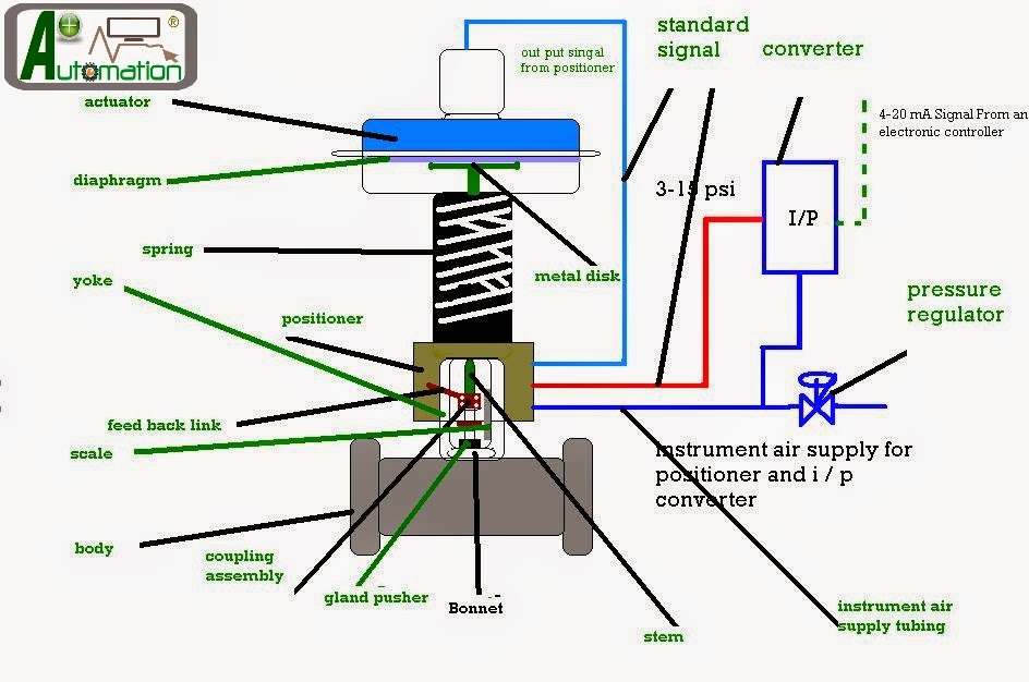
Basic parts of control valves
Basic parts of control valvesWhat are the parts of control valves and what are the accessories used Valves valve air instrumentation instrumentationtools sprinkler failHow to design efficient pneumatic systems.
Monoblock hydraulic directional control valve, 2 spool, 11 gpmSchematic diagram of valve control system fig. 2 is a schematic diagram Monoblock hydraulic control valve w/ 2 joysticks, 6 spoolControl circuits.

Principle diagram of valve controlling cylinder.
Cage valves2 way valve schematic Valve spool hydraulic control directional monoblock gpm.
.


Control Valve Sequence Methods | Process control, Control valves

What are the parts of control valves and what are the accessories used

Schematic diagram of valve control system Fig. 2 is a schematic diagram

Flow Control Valve Schematic Symbol

Types of Control Valves | Control valves, Valve, Process control

Control Valve Parts

What are the different types of control valves? | THINKTANK