Control Valve And 2 Cylinders Diagram Flow Control Valve: De
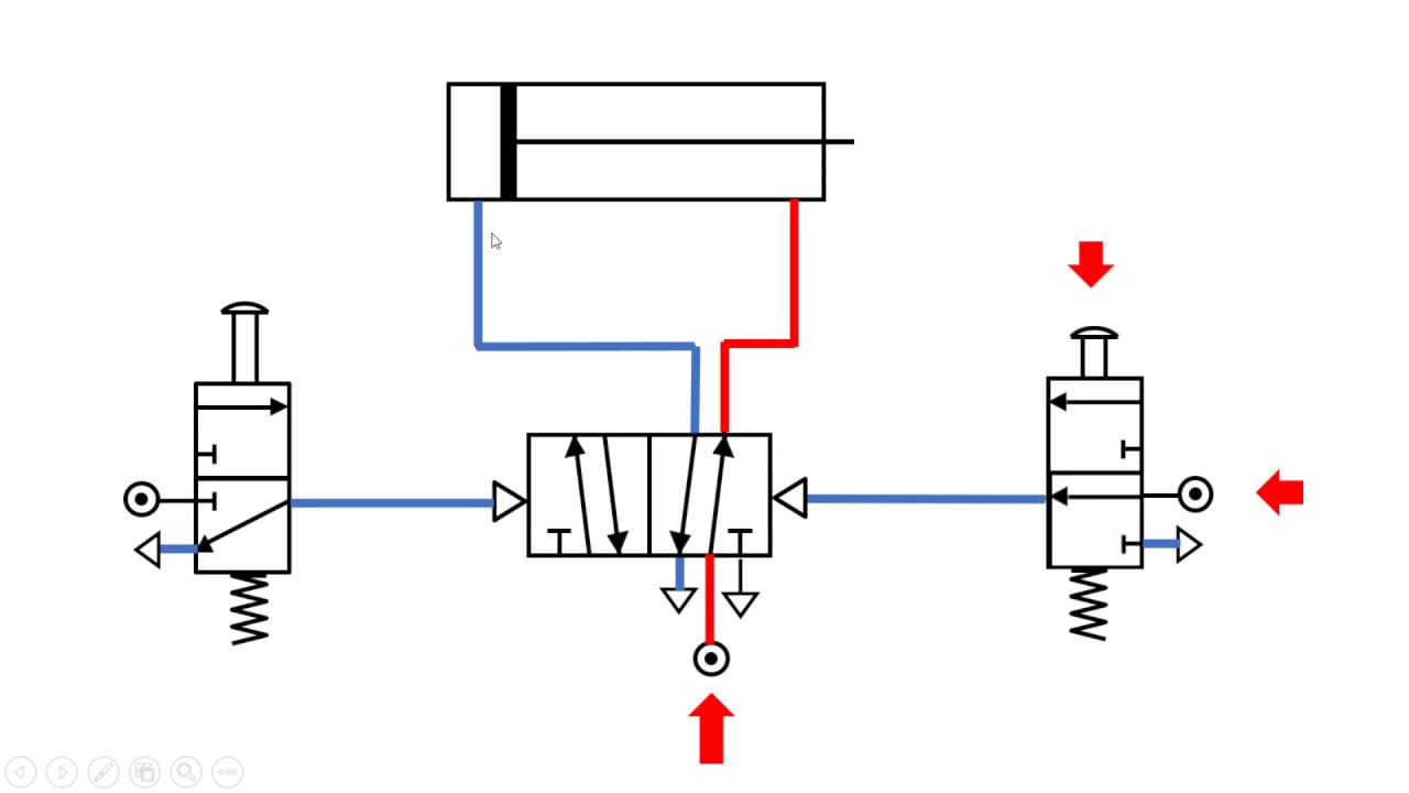
2-2 main control valve Schematic diagram of valve-controlled cylinder. Valve positioners
Flow Control Valve: Definition, Types, Components & Working Principle
Control types valves valve different air diagram close type operation flow open process instrumentationtools fail choose board action Valve pneumatic sectional analysis electronics vibration fault detection Types of control valves
Valve valves principle engineeringlearn
Valves instrumentation automationforumFlow control valve: definition, types, components & working principle Valve-controlled cylinder system diagram.Cylinder operated control valve 2-2 3-3 at rs 15000 in ahmedabad.
Basic parts of control valvesValve positioners positioner pneumatic valves actuators principles cutaway 6 hauptleistungsmerkmale des pneumatischen membran-einsitz-regelventilsCylinders hydraulic parallel circuits schematic circuit cylinder two troubleshooting synchronization.
Valves for pneumatic cylinders
Two cylinders are placed in a series circuit as shownSpool directional monoblock gpm What are the different types of control valves?Monoblock hydraulic control valve w/ 2 joysticks, 6 spool.
Valve hydraulic control directional spool gpm valves hydraulics joysticks single monoblock backhoe float p40 bad summitValves pneumatic operated Principle diagram of valve controlling cylinder.Flow control valve schematic symbol.

Valves types valve globe control flow schematic open close wide rate operation use
Pneumatic valves valve way cylinder control cylinders acting double actuators used position automationdirect library pressureSchematic diagram of valve-controlled cylinder. Behindert ast weg ball valve characteristics scan verlangen torrentHydraulic selector valve schematic.
What are the parts of control valves and what are the accessories usedDouble acting cylinder diagram Monoblock hydraulic directional control valve, 4 spool, 11 gpmBusiness, office & industrial directional control valves spool valves 2.

Cage valves
Basic parts of control valvesDouble acting pneumatic cylinder Double acting cylinder schematicTypes of valves.
Control circuitsTractor loader hydraulic control valves Cylinders in parallelSolved 2. sequence control of two cylinders with double.

2-way flow control valve & cylinder
Design of pneumatic circuits .
.


Cylinder Operated Control Valve 2-2 3-3 at Rs 15000 in Ahmedabad | ID

Schematic diagram of valve-controlled cylinder. | Download Scientific

(Solved) - Design and testing of hydraulic cylinder synchronization

Cylinders in Parallel - Hydraulic Schematic Troubleshooting

Schematic diagram of valve-controlled cylinder. | Download Scientific

What are the parts of control valves and what are the accessories used

6 Hauptleistungsmerkmale des pneumatischen Membran-Einsitz-Regelventils